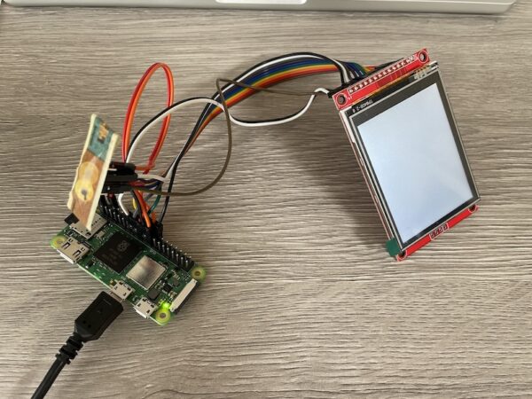
raspberry pi zero 2 wでタッチ液晶ST7789+XPT2046を操作しようと試みました。
購入
液晶は2.8inch TFT 240×320 with touchという広く出回っているタイプ。アリエクにて800円前後で購入。
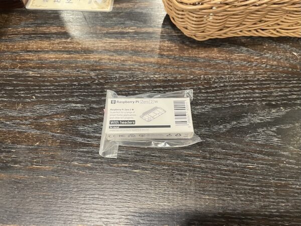
アリエクで購入したraspberry piは壊れていたので返送して、秋月でraspberry pi zero 2 wを購入しました。
テストの手順とトラブルシュート
OS書き込み
初めてのraspberry pi zero 2 wということで、raspberry pi imagerを使って 2GB micro sdカードにOSをインストールするものの、エラーで書き込みが終了しない。
16 GBにしたら無事終了しました。イメージ容量が足りなかったみたい。容量が足りないというエラーメッセージがでないのはなぜ。
64bitのほうが処理が早いそうなので、64bit baspberry pi osに。イメージ容量は1.1 GBだけど展開すると膨らむのかも。
オプションでwifiとsshを有効にし、wifiの方は国をJPに設定するのを忘れずに。
配線
LCDをSPI0, 0、タッチをSPI0, 1と配線した。
## 配線(SPI0を使用)
電圧はすべて3.3V系で統一します。

### ST7789(液晶) → Raspberry Pi
VCC → 3V3(ピン1)
GND → GND(ピン6)
SCL/CLK → GPIO11 / SCLK(ピン23)
SDA/MOSI → GPIO10 / MOSI(ピン19)
CS → GPIO8 / CE0(ピン24)
DC → GPIO25(ピン22)
RST → GPIO24(ピン18)
LED/BL(バックライト) → 3V3

### XPT2046(抵抗膜タッチ想定) → Raspberry Pi

T_CLK → GPIO11 / SCLK(ピン23)
T_DIN → GPIO10 / MOSI(ピン19)
T_DO → GPIO9 / MISO(ピン21)
T_CS → GPIO7 / CE1(ピン26)
T_IRQ(=PENIRQ) → GPIO22(ピン15)
raspi-configでspiを有効にし、aptでドライバ・ライブラリをインストール
sudo raspi-config nonint do_spi 0
sudo apt update
sudo apt install -y python3-pil python3-spidev python3-evdev evtest
python3 -m pip install --break-system-packages st7789
タッチは動く
/boot/firmware/config.txtに次を追記する。
# /boot/firmware/config.txt に追記
dtparam=spi=on
dtoverlay=ads7846,cs=1,penirq=22,penirq_pull=2,xohms=100,speed=2000000
evtestでタッチ動作チェックok
$ evtest
No device specified, trying to scan all of /dev/input/event*
Not running as root, no devices may be available.
Available devices:
/dev/input/event0:	vc4-hdmi
/dev/input/event1:	vc4-hdmi HDMI Jack
/dev/input/event2:	ADS7846 Touchscreen
Select the device event number [0-2]: 2
Input driver version is 1.0.1
Input device ID: bus 0x1c vendor 0x0 product 0x1ea6 version 0x0
Input device name: "ADS7846 Touchscreen"
Supported events:
  Event type 0 (EV_SYN)
  Event type 1 (EV_KEY)
    Event code 330 (BTN_TOUCH)
  Event type 3 (EV_ABS)
    Event code 0 (ABS_X)
      Value      0
      Min        0
      Max     4095
    Event code 1 (ABS_Y)
      Value      0
      Min        0
      Max     4095
    Event code 24 (ABS_PRESSURE)
      Value      0
      Min        0
      Max    65535
Properties:
Testing ... (interrupt to exit)
Event: time 1757663890.352177, type 1 (EV_KEY), code 330 (BTN_TOUCH), value 1
Event: time 1757663890.352177, type 3 (EV_ABS), code 0 (ABS_X), value 1209
Event: time 1757663890.352177, type 3 (EV_ABS), code 1 (ABS_Y), value 2085
Event: time 1757663890.352177, type 3 (EV_ABS), code 24 (ABS_PRESSURE), value 65310
Event: time 1757663890.352177, -------------- SYN_REPORT ------------
Event: time 1757663890.364013, type 1 (EV_KEY), code 330 (BTN_TOUCH), value 0
Event: time 1757663890.364013, type 3 (EV_ABS), code 24 (ABS_PRESSURE), value 0
pythonからライブラリを使っても動く。
# read_touch.py
import evdev

dev = None
for path in evdev.list_devices():
    d = evdev.InputDevice(path)
    if "ADS7846" in d.name:
        dev = d
        break

assert dev, "ADS7846 Touchscreenが見つかりません"

x = y = p = None
for e in dev.read_loop():
    if e.type == evdev.ecodes.EV_ABS:
        if e.code == evdev.ecodes.ABS_X: x = e.value
        elif e.code == evdev.ecodes.ABS_Y: y = e.value
        elif e.code == evdev.ecodes.ABS_PRESSURE: p = e.value
        if None not in (x, y, p):
            # 必要なら xmin..ymax から 0..239/0..319 へ線形マップ
            print("raw:", x, y, p)
$ python read_touch.py
raw: 1340 2846 65353
raw: 1313 2846 65353
raw: 1313 2822 65353
raw: 1313 2822 65352
raw: 1265 2822 65352
raw: 1265 2801 65352
raw: 1265 2801 65360
raw: 1230 2801 65360
LCD ST7789は動かず。spidev0.0がない。
そもそも、/dev/spidev0.0がNo such file or directoryで出てこない。
$ ls /dev/spidev*
ls: cannot access '/dev/spi*': No such file or directory

$ ls /sys/bus/spi/devices
spi0.1

$ lsmod | grep spidev || sudo modprobe spidev

$ dmesg | grep -i spidev

$ uname -a
Linux rpzero2w 6.12.34+rpt-rpi-v8 #1 SMP PREEMPT Debian 1:6.12.34-1+rpt1~bookworm (2025-06-26) aarch64

$ dmesg | grep spi
[    7.927731] ads7846 spi0.1: supply vcc not found, using dummy regulator
[    7.934708] ads7846 spi0.1: touchscreen, irq 184
[    7.935341] input: ADS7846 Touchscreen as /devices/platform/soc/3f204000.spi/spi_master/spi0/spi0.1/input/input2
フレームバッファ(fbtft)では液晶は動く
/boot/firmware/config.txtに、次のようにdtoverlay=fbtftを追加すると、起動時のコンソールは液晶に表示される。
# /boot/firmware/config.txt
dtparam=spi=on
dtoverlay=ads7846,cs=1,penirq=22,penirq_pull=2,xohms=100,speed=2000000
dtoverlay=fbtft,spi0-0,st7789v,reset_pin=24,dc_pin=25,rotate=270,width=240,height=320
なので、配線は間違っていないし、液晶も壊れていない。液晶に載っているチップもST7789で間違いない。そもそも/dev/spidev0.0が存在しないので、raspberry pi osのソフトウェア側に問題があるということ。
なお、fbtftが有効の状態では /sys/bus/spi/devices/spi0.0は存在するようになったが、やはり/dev/spidev0.0はありません。
$ ls -l /dev/spidev0.0
ls: cannot access '/dev/spidev0.0': No such file or directory

$ ls /sys/bus/spi/devices
spi0.0 spi0.1

$ lsmod | egrep 'spi_bcm2835|spidev'
spi_bcm2835 20480 0
これはfbtftがspi0.0 をドライバで占有しているため。fbtft を有効にすると、そのCSには spidev ノードは作られない。(ユーザー空間からは開けません)
この状態でフレームバッファで液晶に描画することはできました。
# fb_draw.py
import mmap, os
from PIL import Image

W, H = 240, 320
fb = open("/dev/fb0", "r+b") # or /dev/fb1とか
mm = mmap.mmap(fb.fileno(), W*H*2, mmap.MAP_SHARED, mmap.PROT_WRITE)

def show(img):
    img = img.convert("RGB").resize((W, H))
    buf = bytearray()
    for r,g,b in img.getdata():
        v = ((r & 0xF8)<<8) | ((g & 0xFC)<<3) | (b>>3)  # RGB565
        buf += bytes([(v>>8)&0xFF, v&0xFF])
    mm.seek(0); mm.write(buf)

show(Image.new("RGB",(W,H),(0,255,0)))  # 緑一色
でもユーザー空間から操作したいので、dtoverlay=fbtftの行は削除しておく。配線の確認はとれたので、あとはドライバを試行錯誤することにする。(ここまでで半日使ったという)
dtoverlay=ads7846が邪魔をしている
タッチ操作用のdtoverlay=ads7846も消す
# /boot/firmware/config.txt
dtparam=spi=on
# dtoverlay=ads7846,cs=1,penirq=22,penirq_pull=2,xohms=100,speed=2000000
するとls -l /dev/spidev0.0が出てくる。
$ ls -l /dev/spidev*
crw-rw---- 1 root spi 153, 0 Sep 13 07:39 /dev/spidev0.0
crw-rw---- 1 root spi 153, 1 Sep 13 07:39 /dev/spidev0.1
$ ls /sys/bus/spi/devices
spi0.0  spi0.1
なので、ads7846が邪魔をしているよう。dtoverlay=ads7846を戻すと、やはりspidev0.0が消える。
dtoverlay=spi0-0cs、dtoverlay=spi0-1csなどと追記して、spidevはCS0などと明示すると、ads7846を使ってもspidev0.0が残るかも、という話もありました。
# /boot/firmware/config.txt
dtparam=spi=on
dtoverlay=spi0-1cs
dtoverlay=ads7846,cs=1,penirq=22,penirq_pull=2,xohms=100,speed=2000000
でも、dtoverlay=ads7846を書くと、やはりspidev0.0が消えます。
Pimoroni st7789は動かない
config.txtを次だけにして、/dev/spidev0.0がある状態で液晶の動作チェックをします。
# /boot/firmware/config.txt
dtparam=spi=on
pythonのライブラリ・モジュールst7789は、動きませんでした。
# st7789_pimoroni_test.py
from PIL import Image
import st7789

disp = st7789.ST7789(
    port=0, cs=0, dc=25, rst=24,
    width=240, height=320,
    rotation=0,
    spi_speed_hz=8_000_000,
    offset_left=0, offset_top=0
)
disp.begin()
disp.display(Image.new("RGB", (240,320), (0,255,0)))
このライブラリの初期化シーケンスと、接続しているST7789V系液晶ドライバチップが合っていない可能性が高い。
SPIの動作チェック
/dev/spidev0.0がある状態で。
$ python3 - <<'PY'
import spidev
spi=spidev.SpiDev(); spi.open(0,0)
spi.max_speed_hz=8_000_000; spi.mode=0
spi.xfer2([0x00]*10)
print("SPI OK"); spi.close()
PY
SPI OKSPIバスを開くことは出来ています。
luma.lcdなら動く
$ python3 -m pip install --break-system-packages luma.lcd luma.core pillow# luma_test.py
from PIL import Image
from luma.core.interface.serial import spi
from luma.lcd.device import st7789
W,H = 240,320
# まず mode=0 で試す。映らなければ 3 でも試す
serial = spi(port=0, device=0, gpio_DC=25, gpio_RST=24,
bus_speed_hz=8_000_000, spi_mode=0) # ← 0がダメなら3
dev = st7789(serial, width=W, height=H, rotate=0, bgr=True) # bgr=True で配線差吸収
img = Image.new("RGB", (W,H), "green")
dev.display(img)
表示は luma.lcd、タッチはADS7846を使わずユーザー空間でXPT2046を読む
この方法しか動かないことがわかった。いつも通りのlinuxのグタグタ感。設定変更して再起動で2~3分使うので、試行錯誤の回数が増やせない。pentiumにlinuxを入れるような時代もこんな感じでした。ファイルシステムを使いたいならzeroでも仕方ないが、GPIO, 簡易httpサーバを使うだけならpi pico 2 wのほうが良さそう。
タッチをしたところに黒点を打つデモコード。一応ここまで走るようにはなったが、次は点の位置がずれる問題。
# xpt2046_calib_and_demo_ascii.py
# Display: luma.lcd ST7789 (SPI0 CE0)
# Touch:   XPT2046 via spidev (SPI0 CE1), IRQ=GPIO22
# Requirements: pip install luma.lcd luma.core pillow RPi.GPIO spidev

from PIL import Image, ImageDraw
from statistics import median
import time, spidev, RPi.GPIO as GPIO
from luma.core.interface.serial import spi
from luma.lcd.device import st7789 as LCD

# -------- LCD setup --------
W, H = 240, 320
serial = spi(port=0, device=0, gpio_DC=25, gpio_RST=24,
             bus_speed_hz=8_000_000, spi_mode=0)  # if no image, try spi_mode=3
dev = LCD(serial, width=W, height=H, rotate=0, bgr=True)

# -------- Touch(XPT2046) setup --------
IRQ = 22  # PENIRQ
GPIO.setmode(GPIO.BCM)
GPIO.setup(IRQ, GPIO.IN, pull_up_down=GPIO.PUD_UP)

tp = spidev.SpiDev()
tp.open(0, 1)                 # bus=0, cs=1
tp.max_speed_hz = 2_000_000
tp.mode = 0

def read12(cmd: int) -> int:
    # XPT2046: send cmd, then read 12-bit result from next two bytes
    hi, lo = tp.xfer2([cmd, 0x00, 0x00])[1:]
    return ((hi << 8) | lo) >> 3

def sample_xy(n=8, dt=0.001):
    xs, ys = [], []
    for _ in range(n):
        y = read12(0x90)  # Y first
        x = read12(0xD0)  # then X
        xs.append(x); ys.append(y)
        time.sleep(dt)
    return int(median(xs)), int(median(ys))

def pressed() -> bool:
    return GPIO.input(IRQ) == 0

def wait_release():
    while pressed():
        time.sleep(0.003)

# -------- draw helpers (no text) --------
def show_cross(x, y, bg="black"):
    img = Image.new("RGB", (W, H), bg)
    d = ImageDraw.Draw(img)
    s = 8
    d.line((x - s, y, x + s, y), fill="white", width=2)
    d.line((x, y - s, x, y + s), fill="white", width=2)
    d.ellipse((x-6, y-6, x+6, y+6), outline="white", width=2)
    dev.display(img)

def show_point(x, y, color="white"):
    img = Image.new("RGB", (W, H), "black")
    d = ImageDraw.Draw(img)
    d.ellipse((x-3, y-3, x+3, y+3), fill=color)
    dev.display(img)

# -------- 4-point calibration (ASCII-only UI) --------
targets = [("TL", 20, 20),
           ("TR", W-20, 20),
           ("BR", W-20, H-20),
           ("BL", 20, H-20)]

print("Calibration: touch targets in order -> TL, TR, BR, BL")
raw = []
for name, sx, sy in targets:
    show_cross(sx, sy)
    # wait for press
    t0 = time.time()
    while not pressed():
        if time.time() - t0 > 20:
            raise SystemExit("Timeout waiting for touch")
        time.sleep(0.003)
    xr, yr = sample_xy()
    raw.append((xr, yr))
    wait_release()

if len(raw) < 3:
    tp.close(); GPIO.cleanup()
    raise SystemExit("Not enough samples")

# Decide swap/invert using geometry
# spans
xs = [r[0] for r in raw]; ys = [r[1] for r in raw]
xspan = max(xs) - min(xs); yspan = max(ys) - min(ys)
SWAPXY = False
if (W > H and yspan > xspan) or (H > W and xspan > yspan):
    SWAPXY = True

# order: TL, TR, BR, BL
LU, RU, RD, LD = raw

rx_idx, ry_idx = (1, 0) if SWAPXY else (0, 1)
INVERTX = not ((RU[rx_idx] - LU[rx_idx]) > 0)
INVERTY = not ((LD[ry_idx] - LU[ry_idx]) > 0)

# ranges from corners
if SWAPXY:
    rx = [r[1] for r in raw]  # use swapped
    ry = [r[0] for r in raw]
else:
    rx = [r[0] for r in raw]
    ry = [r[1] for r in raw]

XMIN, XMAX = min(rx), max(rx)
YMIN, YMAX = min(ry), max(ry)
# margins for tolerance
MARGIN = 40
XMIN -= MARGIN; XMAX += MARGIN
YMIN -= MARGIN; YMAX += MARGIN

def map_to_screen(x, y):
    if SWAPXY:
        x, y = y, x
    # clamp
    x = XMIN if x < XMIN else XMAX if x > XMAX else x
    y = YMIN if y < YMIN else YMAX if y > YMAX else y
    # scale
    sx = int((x - XMIN) * (W - 1) / max(1, (XMAX - XMIN)))
    sy = int((y - YMIN) * (H - 1) / max(1, (YMAX - YMIN)))
    if INVERTX:
        sx = (W - 1) - sx
    if INVERTY:
        sy = (H - 1) - sy
    return sx, sy

print("Calibration done:",
      f"SWAPXY={SWAPXY} INVERTX={INVERTX} INVERTY={INVERTY}",
      f"X:[{XMIN},{XMAX}] Y:[{YMIN},{YMAX}]")

# -------- Demo loop --------
img = Image.new("RGB", (W, H), "black")
dev.display(img)
try:
    while True:
        if not pressed():
            time.sleep(0.003)
            continue
        # collect short burst
        pts = []
        t0 = time.time()
        while pressed() and time.time() - t0 < 0.2:
            xr, yr = sample_xy()
            pts.append((xr, yr))
            time.sleep(0.003)
        if pts:
            xm = int(median([p[0] for p in pts]))
            ym = int(median([p[1] for p in pts]))
            sx, sy = map_to_screen(xm, ym)
            show_point(sx, sy)
        wait_release()
except KeyboardInterrupt:
    pass
finally:
    tp.close()
    GPIO.cleanup()
タッチを使わず画像を表示するコードでも、白帯があり、色がおかしい。
python3 -m pip install --break-system-packages luma.lcd luma.core pillow# show_jpg_luma.py
from PIL import Image, ImageOps
from luma.core.interface.serial import spi
from luma.lcd.device import st7789
import time
W, H = 240, 320 # 画面サイズ
ROT = 0 # 0=縦, 1=右90°, 2=180°, 3=左90°
serial = spi(
port=0, device=0, # SPI0 / CE0
gpio_DC=25, gpio_RST=24,
bus_speed_hz=8_000_000,
spi_mode=0 # 映らなければ 3 に変更
)
dev = st7789(serial, width=W, height=H, rotate=ROT, bgr=True)
img = Image.open("test.jpg").convert("RGB")
target = (W, H) if ROT in (0,2) else (H, W)
img = ImageOps.fit(img, target, method=Image.Resampling.LANCZOS, centering=(0.5, 0.5))
dev.display(img)
time.sleep(3)液晶の色と位置がおかしい
CMY。
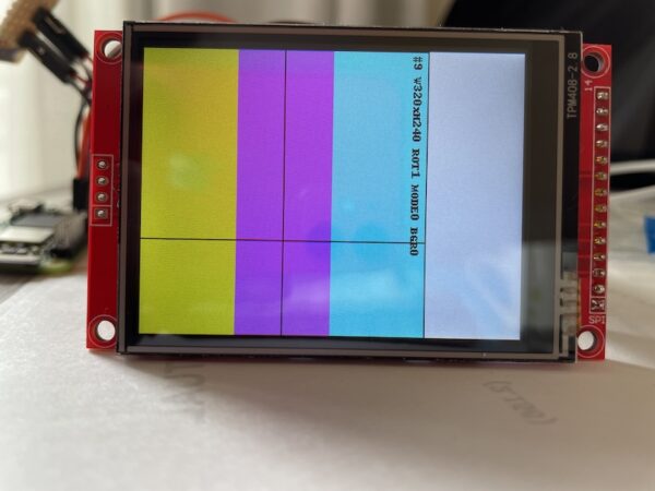
rotateはしているが、offset, bgr, invertは効いていない感じ。
MISOも配線して、本当にST7789なのか確認する。
# read_lcd_id.py
# SPI0 CE0 (bus=0, cs=0), DC=BCM25, RST=BCM24, MISO必須(GPIO9)
import time, spidev, RPi.GPIO as GPIO

BUS, DEV = 0, 0
DC, RST = 25, 24

def hw_reset():
    GPIO.output(RST, GPIO.HIGH); time.sleep(0.05)
    GPIO.output(RST, GPIO.LOW);  time.sleep(0.10)
    GPIO.output(RST, GPIO.HIGH); time.sleep(0.12)

def write_cmd(spi, c):
    GPIO.output(DC, GPIO.LOW)
    spi.xfer2([c])

def read_bytes(spi, n, dummy=1):
    GPIO.output(DC, GPIO.HIGH)
    raw = spi.xfer2([0x00] * (n + dummy))
    return raw[dummy:]

def read_reg(spi, c, n, name):
    write_cmd(spi, c)
    v1 = read_bytes(spi, n, dummy=1)
    write_cmd(spi, c)
    v0 = read_bytes(spi, n, dummy=0)
    print(f"{name:8s} 0x{c:02X} ->", " ".join(f"{x:02X}" for x in v1),
          "| no-dmy:", " ".join(f"{x:02X}" for x in v0))

def main():
    GPIO.setmode(GPIO.BCM)
    GPIO.setup(DC, GPIO.OUT, initial=GPIO.HIGH)
    GPIO.setup(RST, GPIO.OUT, initial=GPIO.HIGH)

    for mode in (0, 3):
        print(f"\n=== SPI mode {mode} ===")
        spi = spidev.SpiDev(); spi.open(BUS, DEV)
        spi.max_speed_hz = 1_000_000
        spi.mode = mode

        hw_reset()
        # よく使う識別系レジスタ
        read_reg(spi, 0x04, 3, "RDDID")      # Display ID
        read_reg(spi, 0x09, 4, "RDDST")      # Status
        read_reg(spi, 0x0A, 1, "RDDPM")      # PowerMode
        read_reg(spi, 0x0B, 1, "RDDMAD")     # MADCTL
        read_reg(spi, 0x0C, 1, "RDDCOL")     # COLMOD
        read_reg(spi, 0xD3, 4, "RDID4")      # ID4
        read_reg(spi, 0xDA, 1, "RDID1")
        read_reg(spi, 0xDB, 1, "RDID2")
        read_reg(spi, 0xDC, 1, "RDID3")

        spi.close()

    GPIO.cleanup()

if __name__ == "__main__":
    main()
=== SPI mode 0 ===
RDDID    0x04 -> 40 D9 C0 | no-dmy: 00 40 D9
RDDST    0x09 -> 30 80 00 00 | no-dmy: 00 30 80 00
RDDPM    0x0A -> 00 | no-dmy: 00
RDDMAD   0x0B -> 00 | no-dmy: 00
RDDCOL   0x0C -> 00 | no-dmy: 00
RDID4    0xD3 -> 00 00 00 00 | no-dmy: 00 00 00 00
RDID1    0xDA -> 00 | no-dmy: 00
RDID2    0xDB -> 00 | no-dmy: 00
RDID3    0xDC -> 00 | no-dmy: 00
40 D9 ということで、ST7789であることは間違いなさそう。
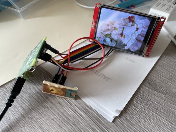
lumaライブラリを使わずrawコマンドだと正常
offset 0,0で色も正しく表示されます。
# st7789_show_final.py
# HW: SPI0/CE0 (SCLK=GPIO11, MOSI=GPIO10, CS=GPIO8), DC=BCM25, RST=BCM24, BL=3V3
# 前提: /boot/firmware/config.txt は dtparam=spi=on のみ
import time, spidev, RPi.GPIO as GPIO
from PIL import Image, ImageOps, ImageDraw

# ---- 固定値 ----
BUS, DEV     = 0, 0
DC, RST      = 25, 24
W, H         = 240, 320
XOFF, YOFF   = 0, 0          # ← 0,0 でOK
SPI_HZ       = 8_000_000
SPI_MODE     = 0             # 0でOK(3でも可)
BGR_ORDER    = True          # そのままでOK
CHUNK        = 4096

# ---- MADCTL bits ----
MY, MX, MV = 0x80, 0x40, 0x20
BGRBIT     = 0x08
def madctl(rot: int) -> int:
    base = (BGRBIT if BGR_ORDER else 0x00)
    if rot == 0:  return base
    if rot == 1:  return base | MX | MV     # 90°(横)
    if rot == 2:  return base | MX | MY     # 180°
    if rot == 3:  return base | MY | MV     # 270°(横)
    return base

def write_cmd(c: int, data: bytes | None = None):
    GPIO.output(DC, GPIO.LOW);  spi.xfer2([c])
    if data:
        GPIO.output(DC, GPIO.HIGH)
        for i in range(0, len(data), CHUNK):
            spi.xfer2(data[i:i+CHUNK])

def set_window(x0,y0,x1,y1):
    write_cmd(0x2A, bytes([x0>>8, x0&0xFF, x1>>8, x1&0xFF]))
    write_cmd(0x2B, bytes([y0>>8, y0&0xFF, y1>>8, y1&0xFF]))
    write_cmd(0x2C)

def rgb565(buf_img):
    out = bytearray()
    for r,g,b in buf_img.convert("RGB").getdata():
        if BGR_ORDER: r,g,b = b,g,r
        v = ((r & 0xF8) << 8) | ((g & 0xFC) << 3) | (b >> 3)
        out += bytes([(v>>8)&0xFF, v&0xFF])
    return out

def hw_reset():
    GPIO.output(RST, GPIO.HIGH); time.sleep(0.05)
    GPIO.output(RST, GPIO.LOW);  time.sleep(0.10)
    GPIO.output(RST, GPIO.HIGH); time.sleep(0.12)

def init_panel(rot=0):
    # 最小限のST7789 240x320初期化(16bpp固定)
    write_cmd(0x01); time.sleep(0.12)      # SWRESET
    write_cmd(0x11); time.sleep(0.12)      # SLPOUT
    write_cmd(0x3A, bytes([0x55]))         # COLMOD=16bpp
    write_cmd(0x36, bytes([madctl(rot)]))  # MADCTL
    # 安定化(一般的な値)
    write_cmd(0xB2, bytes([0x0C,0x0C,0x00,0x33,0x33]))
    write_cmd(0xB7, bytes([0x35]))
    write_cmd(0xBB, bytes([0x19]))
    write_cmd(0xC0, bytes([0x2C]))
    write_cmd(0xC2, bytes([0x01]))
    write_cmd(0xC3, bytes([0x12]))
    write_cmd(0xC4, bytes([0x20]))
    write_cmd(0xC6, bytes([0x0F]))
    write_cmd(0xD0, bytes([0xA4,0xA1]))
    write_cmd(0x20)                        # INVOFF(色反転しない)
    write_cmd(0x29); time.sleep(0.02)      # DISPON

def display_image(img, rot=0):
    target = (W, H) if rot in (0,2) else (H, W)
    img = ImageOps.fit(img.convert("RGB"), target, method=Image.Resampling.LANCZOS)
    # 物理回転はMADCTLで処理するので、画像自体は回さない
    set_window(XOFF, YOFF, XOFF + W - 1, YOFF + H - 1)
    GPIO.output(DC, GPIO.HIGH)
    data = rgb565(img)
    for i in range(0, len(data), CHUNK):
        spi.xfer2(data[i:i+CHUNK])

def test_pattern():
    p = Image.new("RGB",(W,H),"black")
    d = ImageDraw.Draw(p)
    d.rectangle((0,0,W,H//3), fill=(255,0,0))
    d.rectangle((0,H//3,W,2*H//3), fill=(0,255,0))
    d.rectangle((0,2*H//3,W,H), fill=(0,0,255))
    d.rectangle((0,0,W-1,H-1), outline="white")
    d.line((0,H//2,W,H//2), fill="white")
    d.line((W//2,0,W//2,H), fill="white")
    return p

# ---- main ----
if __name__ == "__main__":
    ROT = 0  # 0/1/2/3 好きな向き
    GPIO.setmode(GPIO.BCM)
    GPIO.setup(DC,  GPIO.OUT, initial=GPIO.HIGH)
    GPIO.setup(RST, GPIO.OUT, initial=GPIO.HIGH)
    spi = spidev.SpiDev(); spi.open(BUS, DEV)
    spi.max_speed_hz = SPI_HZ; spi.mode = SPI_MODE
    try:
        hw_reset()
        init_panel(rot=ROT)
        display_image(test_pattern(), rot=ROT)  # パターン
        img = Image.open("test.jpg")
        display_image(img, rot=ROT)             # 画像
        while True: time.sleep(1)               # 表示を維持
    finally:
        spi.close(); GPIO.cleanup()
タッチで絵を描くコード
# paint_st7789_xpt2046_deglitch.py
# LCD: SPI0/CE0  DC=BCM25 RST=BCM24
# TP : SPI0/CE1  IRQ=BCM22
import time, spidev, RPi.GPIO as GPIO
from PIL import Image

# ==== あなたの環境値を入れる ====
BUS_LCD, DEV_LCD = 0,0
BUS_TP,  DEV_TP  = 0,1
DC, RST, IRQ = 25,24,22
W,H = 240,320
SPI_HZ_LCD=8_000_000; SPI_MODE_LCD=0; BGR_ORDER=True
CHUNK=4096

# ==== マッピング(必要なら調整)====
XMIN,XMAX = 200,3900
YMIN,YMAX = 200,3900
SWAPXY=False; INVERTX=True; INVERTY=False   # ← INVERTX=True

# ==== 外れ値/離す瞬間対策パラメータ ====
EDGE_RAW = 80       # これ未満/超は無効
Z1_MIN   = 40       # 押圧が弱すぎると無効
Z2_MAX   = 4000     # 離れかけ無効
JUMP_PX  = 35       # 1サンプルでの最大許容移動(px)

# ---------- LCD 低レベル ----------
def _write_chunks(spi, b):
    for i in range(0,len(b),CHUNK): spi.xfer2(b[i:i+CHUNK])
def lcd_cmd(spi,c,d=None):
    GPIO.output(DC,GPIO.LOW); spi.xfer2([c])
    if d: GPIO.output(DC,GPIO.HIGH); _write_chunks(spi, d)
def set_window(spi,x0,y0,x1,y1):
    lcd_cmd(spi,0x2A,bytes([x0>>8,x0&0xFF,x1>>8,x1&0xFF]))
    lcd_cmd(spi,0x2B,bytes([y0>>8,y0&0xFF,y1>>8,y1&0xFF]))
    lcd_cmd(spi,0x2C)
def rgb565_bytes(img):
    out=bytearray()
    for r,g,b in img.convert("RGB").getdata():
        if BGR_ORDER: r,g,b = b,g,r
        v=((r&0xF8)<<8)|((g&0xFC)<<3)|(b>>3)
        out+=bytes([(v>>8)&0xFF,v&0xFF])
    return out
def rect_fill(spi,x,y,w,h,color=(255,255,255)):
    r,g,b=color;
    if BGR_ORDER: r,g,b=b,g,r
    v=((r&0xF8)<<8)|((g&0xFC)<<3)|(b>>3)
    px=bytes([(v>>8)&0xFF,v&0xFF]); line=px*w
    set_window(spi,x,y,x+w-1,y+h-1); GPIO.output(DC,GPIO.HIGH)
    for _ in range(h): _write_chunks(spi,line)
def lcd_reset():
    GPIO.output(RST,1); time.sleep(0.05); GPIO.output(RST,0); time.sleep(0.10); GPIO.output(RST,1); time.sleep(0.12)
def lcd_init(spi):
    lcd_cmd(spi,0x01); time.sleep(0.12)
    lcd_cmd(spi,0x11); time.sleep(0.12)
    lcd_cmd(spi,0x3A,bytes([0x55]))                  # 16bpp
    lcd_cmd(spi,0x36,bytes([0x08 if BGR_ORDER else 0x00]))
    for c,d in [(0xB2,[0x0C,0x0C,0x00,0x33,0x33]),(0xB7,[0x35]),(0xBB,[0x19]),(0xC0,[0x2C]),(0xC2,[0x01]),(0xC3,[0x12]),(0xC4,[0x20]),(0xC6,[0x0F]),(0xD0,[0xA4,0xA1])]:
        lcd_cmd(spi,c,bytes(d))
    lcd_cmd(spi,0x20)                                 # INVOFF
    lcd_cmd(spi,0x29); time.sleep(0.02)
    rect_fill(spi,0,0,W,H,(20,20,20))                 # 暗灰で初期化

# ---------- XPT2046 ----------
def tp_open():
    tp=spidev.SpiDev(); tp.open(BUS_TP,DEV_TP); tp.max_speed_hz=2_000_000; tp.mode=0; return tp
def read12(tp,cmd):
    hi,lo=tp.xfer2([cmd,0x00,0x00])[1:]; return ((hi<<8)|lo)>>3
def pressed(): return GPIO.input(IRQ)==0

def sample_valid(tp, n=7, dt=0.001):
    # 押圧チェック → 位置サンプル → 途中で離れたら捨てる
    z1=read12(tp,0xB0); z2=read12(tp,0xC0)
    if z1<Z1_MIN or z2>Z2_MAX or not pressed(): return None
    xs,ys=[],[]
    for _ in range(n):
        y=read12(tp,0x90); x=read12(tp,0xD0)
        if not pressed(): return None
        xs.append(x); ys.append(y); time.sleep(dt)
    xs.sort(); ys.sort()
    x=xs[n//2]; y=ys[n//2]           # median
    if x<EDGE_RAW or x>4095-EDGE_RAW or y<EDGE_RAW or y>4095-EDGE_RAW:
        return None
    if SWAPXY: x,y=y,x
    # map
    x=max(XMIN,min(XMAX,x)); y=max(YMIN,min(YMAX,y))
    sx=int((x-XMIN)*(W-1)/max(1,(XMAX-XMIN)))
    sy=int((y-YMIN)*(H-1)/max(1,(YMAX-YMIN)))
    if INVERTX: sx=(W-1)-sx
    if INVERTY: sy=(H-1)-sy
    return sx,sy

# ---------- お絵描き ----------
def clamp(v,lo,hi): return lo if v<lo else hi if v>hi else v
def draw_brush(spi,cx,cy,r=3,color=(255,255,255)):
    x0=clamp(cx-r,0,W-1); y0=clamp(cy-r,0,H-1); x1=clamp(cx+r,0,W-1); y1=clamp(cy+r,0,H-1)
    rect_fill(spi,x0,y0,x1-x0+1,y1-y0+1,color)
def draw_line(spi,x0,y0,x1,y1,r=3,color=(255,255,255)):
    dx=x1-x0; dy=y1-y0; steps=max(abs(dx),abs(dy))
    if steps==0: draw_brush(spi,x0,y0,r,color); return
    for i in range(steps+1):
        x=x0+dx*i//steps; y=y0+dy*i//steps
        draw_brush(spi,x,y,r,color)

def main():
    GPIO.setmode(GPIO.BCM)
    GPIO.setup(DC,GPIO.OUT,initial=GPIO.HIGH)
    GPIO.setup(RST,GPIO.OUT,initial=GPIO.HIGH)
    GPIO.setup(IRQ,GPIO.IN,pull_up_down=GPIO.PUD_UP)

    lcd=spidev.SpiDev(); lcd.open(BUS_LCD,DEV_LCD)
    lcd.max_speed_hz=SPI_HZ_LCD; lcd.mode=SPI_MODE_LCD
    lcd_reset(); lcd_init(lcd)
    tp=tp_open()

    last=None; brush=3; color=(220,220,220)
    try:
        while True:
            if not pressed():
                last=None; time.sleep(0.003); continue
            p=sample_valid(tp)
            if p is None: continue
            sx,sy=p
            if last is None:
                draw_brush(lcd,sx,sy,brush,color)
            else:
                # 急激なジャンプは「ペン離し」とみなして捨てる
                if abs(sx-last[0])+abs(sy-last[1]) > JUMP_PX:
                    if not pressed(): last=None; continue
                draw_line(lcd,last[0],last[1],sx,sy,brush,color)
            last=(sx,sy)
    except KeyboardInterrupt:
        pass
    finally:
        tp.close(); lcd.close(); GPIO.cleanup()

if __name__ == "__main__":
    main()
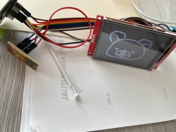
まとめ
raspberry pi zero 2 wはドライバとかライブラリ周りが十分に整備されておらず、ドキュメントもない。そのため、試行錯誤するのが目的でなければ、使わないほうがよいかも。